- Posts
- Renewable heat
Control of large-scale solar thermal systems
Hugues Defreville
Control system, the centerpiece of our plants safety and performance
Today, let’s focus on how we control our installations!
As energy production facilities become increasingly complex, they can no longer be managed manually by one or more on-site operators. The days when a train conductor simply added coal to the boiler to adjust the train’s speed are long gone!
The use of automatic control systems has greatly expanded with the advent of computer technology and wireless communication technologies.
These systems enable the rapid collection of information and quick decision-making, allowing real-time optimization of facilities performance and ensuring their safety.
We’ll tell you more in the following article.
What is systems control ?
Control can be defined as the set of systems/equipment/resources within an installation that automatically measure physical parameters and determine the positions of the system’s actuators while ensuring the regulation and protection of the installation.
The equipment:
To implement an automatic control system, it’s necessary to have a chain for acquiring information and controlling actuators.
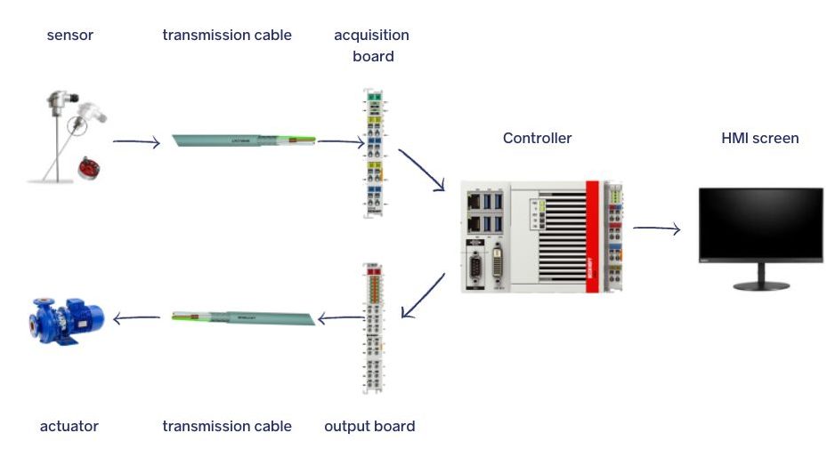
This consists of:
- Analog sensors: They measure various physical parameters such as temperature, pressure, or flow. They convert these parameters into analog signals, typically in the form of currents ranging from 4 mA to 20 mA. For example, a temperature sensor can translate water temperature in the circuit into an electrical current ranging from 4 mA (corresponding to 0°C) to 20 mA (corresponding to 100°C).
- Digital sensors: They indicate the position of an actuator (open or closed) or the exceeding of a threshold. They provide information that will be interpreted as 1 or 0. In practice, they are often like “switches” carrying a low current.
- Cables: They serve as connections, allowing the centralization of analog and digital information from all the equipment in the installation.
- Data acquisition cards (inputs): They retrieve all the electrical signals from different equipment and transform them into information that can be read by a controller.
- Control cards (outputs): They translate the commands from the controller into electrical signals that are then sent to the actuators.
- Actuators: These are all the controlled devices that can influence the operation of the installation, for example, motorized valves, pumps, etc.
- Controller: It collects all the information and analyzes it to determine the commands for the actuators. In each cycle (for example, every 10 milliseconds), it checks the transition conditions between different operating modes and determines the new setpoints for the actuator positions.
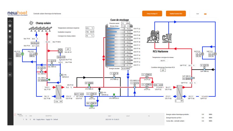
- HMI (Human-Machine Interface): It allows an operator to interact with the plant. It typically consists of a supervisory screen where physical parameters are displayed using a schematic representation of the installation, as shown here:
The Program:
To ensure the operation of the entire system, the program coded in the controller automatically determines the actions to be taken based on measurements, without human intervention, with a response time of less than one second. We can distinguish between two levels of the program:
- High-level: This encompasses the “operating modes” of an installation that characterize its functioning as well as the “transitions” between these modes. For example, the installation can either be in “stand-by” (off) or in “Production” (operational), and a condition determines whether it is in one mode or the other (for a solar thermal installation, solar irradiation is measured, and if it exceeds a threshold, a transition occurs).
To represent the various modes that make up a program and the different transitions, the representation in the form of “GRAFCET” is often used.
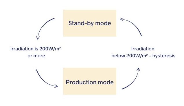
As seen in the example above, the condition for transitioning from one mode to another, in one direction, is slightly different from the condition in the other direction to prevent the program from rapidly switching back and forth between modes if the measured value is close to the threshold. This is known as “chattering.” A simple solution to avoid this phenomenon is the implementation of “hysteresis,” which is a small value that shifts the return threshold to the previous mode. In the example presented above, we would wait for the irradiation to drop below 190 (200-10) W/m² before returning to the “stand-by” mode.
- Low-level: Once the operating mode is defined (e.g., “Production”), regulators continuously adjust the positions of actuators to optimize performance. In the case of a pump with a variable-speed drive, the pump’s rotational speed is regulated to control the fluid flow rate.
The best known of these regulators is the PID (Proportional Integral Derivative), which corrects the actuator’s position based on the direct comparison of the measured value to the setpoint while also taking into account the overall deviations observed at each previous time step and possibly the system’s dynamics. If you press the accelerator pedal of a car to go from 0 to 100 km/h and don’t release it slightly as you approach 100 km/h, there is a high risk of exceeding that speed.
Control of a solar thermal plant
A solar thermal installation requires a number of different modes for optimum operation.
The system cannot be shut down on demand, as it is directly dependent on the presence of sunlight.
These are the main modes:
- “Stand-by” mode: the system is switched off when there is no irradiation, for example at night, when there is no fluid circulation.
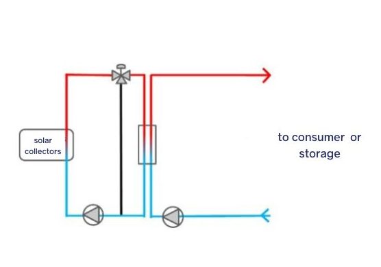
- This is followed by “preheating” mode. The fluid in the solar circuit is heated before switching to “production” mode. When the irradiation starts to be high enough (around 200W/m²), the solar collectors are able to produce heat, but the solar circuit, which contains a large quantity of fluid (several tens of m3), needs to be “pre-heated” before it reaches a temperature that can be used. To do this, the fluid must be circulated in a loop in the solar field so that it reaches the set temperature (90°C, for example).
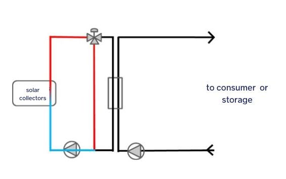
- Once the fluid temperature has reached the set temperature, the system can switch to “production” mode to send the heat produced to the consumer or an energy storage system. In this mode, the fluid in the solar circuit is directed to the heat exchanger and the pump on the consumer/storage side is switched on to start exchanging heat with its circuit.
The solar circuit pump is then regulated to reach the set temperature at the solar array outlet. To do this, a model based approach is used that takes into account the external conditions (temperature, irradiation), the temperature of the fluid at the solar array inlet and the performance coefficients of the solar collectors, in order to determine the theoretical flow rate required to obtain the desired temperature at the solar array outlet.
This is an “open” control loop, as it is not possible to regulate the flow rate solely by comparing the temperature measured at the array outlet with the set point. This is because the operating conditions, and in particular the solar irradiation, are dynamic and constantly changing, while the system itself has a high thermal inertia (the time between the water molecule entering the solar array and leaving it at the other end can be several tens of minutes).
There is, however, a second “closed” control loop cascaded from the “open” loop, in order to adjust the flow rate if necessary according to the measured return temperature (certain physical parameters being difficult to model: wind, dust, etc.).
On the consumer/storage side, the pump will be regulated to achieve the same heat flow rate (flow rate multiplied by the heat capacity of the fluid) in order to maximise heat exchange between the two circuits and optimise the overall performance of the solar thermal installation.

In addition to these main modes, there are also all the safety modes of the installation, in particular :
- Overheating prevention: if there is not enough heat being consumed in relation to what is being produced, and it is no longer possible to store the excess heat, then an overheating prevention mode is activated. Without this heat limitation or evacuation, the system would run the risk of “overheating”, reaching very high temperatures and pressures, which would cause the circuit to drain.
- Antifreeze protection: the solar circuit is filled with glycol water to prevent freezing. However, when outside temperatures are very low for a period of several hours/days, it may be necessary to implement antifreeze protection modes to circulate the fluid in the solar field.
These safety modes make it possible to protect people and property while limiting the electrical consumption of equipment by maximising the thermal energy available to the end consumer. Advanced control strategies are used to achieve this.
Here, we have presented 5 different modes, just for controlling the solar thermal field. If we take into account the management of the heat storage system, the addition of another heat producer (a heat pump, for example) and the different modes of heat supply to the end consumer, we can reach 15 to 20 specific modes for the plant, each with its own particularities and regulations.
Newheat, guarantees reliable and optimised control of its systems
Ultimately, the control of our systems is both the “eyes” and the “brain” of the installation, and must be adapted to each type of system to ensure that performance and safety objectives are met.
It is crucial that the initial design of the installation is carried out in conjunction with the control system (choice of type of equipment, position of probes, etc.) so that all the operating modes can be built in a coherent way and a reliable, durable and high-performance installation can be obtained.
As the designer, builder and operator of its installations, Newheat guarantees a single, coherent control system for the entire heat production, storage and distribution system, which is efficient and constantly optimised thanks to its feedback from operating experience.
Finally, as part of its R&D projects, Newheat is actively working on integrating more complex control methods (based on “self-learning” principles, for example) that will enable it to further improve the performance of its installations and produce as much renewable energy as possible for its industrial and district heating network customers.
If you’ve read this far, and you’re a fan of modelling, regulation, optimisation and control… Newheat is recruiting!